
|
www.riscos.com Technical Support: |
Expansion Cards provide you with a way to add hardware to your RISC OS computer. They plug into slots provided in the computer, typically in the form of a backplane (these are an optional extra on some models).
Extension ROMs are ROMs fitted in addition to the main ROM set, which provide software modules which are automatically loaded by RISC OS on power-on. Note that RISC OS 2 does not support extension ROMs. Extension ROMs are provided so that Acorn can add extra modules to RISC OS, or provide replacement modules for those already in RISC OS. You must not use them.
This chapter gives details of the software that RISC OS provides to manage and communicate with expansion cards. It also gives details of what software and data needs to be provided by expansion cards for RISC OS to communicate with them; in short, all you need to know to write their software. For completeness, it gives the same information for extension ROMs; but - of course - this is irrelevant to you, as you shouldn't use extension ROMs.
The two topics are covered together because both use substantially the same layout of code and data, and the same SWIs. For more details on writing modules, see the chapter entitled Modules.
One thing this chapter does not tell you is how to design expansion card hardware. This is because:
Instead, you should see the further sources of information to which we refer you.
RISC OS computers can support internal slots for expansion cards. If you wish to add more cards than can be fitted to the supplied slots, you must use one of the slots to support an expansion card that buffers the signals on the expansion card bus before passing them on to external expansion cards.
Some RISC OS computers can also support extension ROMs. The availability, size and number of extension ROM sockets depends on which type of RISC OS computer you are using. For example, the A5000 has a single socket for an 8 bit wide ROM.
Expansion cards can have some or all of the following software included:
A wide range of different types of code and data is supported by the Chunk Directories.
The use of the Loader and paged memory has been made as transparent to the end user as possible.
Extension ROMs must include the following software:
In general, RISC OS recognises extension ROMs or ROM sets which are 8, 16 or 32 bits wide, provided the ROM adheres to the specification below. 32 bit wide extension ROM sets are directly executable in place, saving on user RAM. 8 or 16 bit wide sets have to be copied into RAM to execute.
An extension ROM set must end on a 64K boundary or at the start of another extension ROM. This is normally not a problem as it is unlikely you would want to use a ROM smaller than a 27128 (16K), and the normal way of addressing this would mean that the ROM would be visible in 1 byte out of each word, ie within a 64K addressable area.
Extension ROMs must have a 16 byte Extension ROM Header at the end of the ROM image, which indicates the presence of a valid extension ROM. The 'header' is at the end because RISC OS scans the ROM area downwards from the top.
For a ROM image of size n bytes, the format of the header at the end is as follows:
| Byte address | Contents | ||
|---|---|---|---|
| n-16 | 1-word field containing n | ||
| n-12 | 1-word checksum (bottom 32 bits of the sum of all words from addresses 0 to n-16 inclusive) | ||
| n-8 | 2-word id 'ExtnROM0' indicating a valid extension ROM, ie: | ||
| n-8 | &45 | 'E' | |
| n-7 | &78 | 'x' | |
| n-6 | &74 | 't' | |
| n-5 | &6E | 'n' | |
| n-4 | &52 | 'R' | |
| n-3 | &4F | 'O' | |
| n-2 | &4D | 'M' | |
| n-1 | &30 | '0' | |
Note that this header will not necessarily appear in the memory map in the last 16 bytes if the ROM set is 8 or 16 bits wide. In the 8-bit case, the header will appear in one of the four byte positions of the last 16 words, and in the 16-bit case, in one of the two half-word positions of the last 8 words. However, RISC OS copes with this, and uses the mapping of the ID field into memory to automatically derive the width of the extension ROM.
Each expansion card must have an Expansion Card Identity (or ECId) so that RISC OS can tell whether an expansion card is fitted in a backplane slot, and if so, identify it. The ECId may be:
The ECId (whether extended or not) must appear at the bottom of the expansion card space immediately after a reset. However, it does not have to remain readable at all times, and so it can be in a paged address space so long as the expansion card is set to the page containing the ECId on reset.
The ECId is read by a synchronous read of address 0 of the expansion card space. You may only assume it is valid from immediately after a reset until when the expansion card driver is installed.
As well as the Extension ROM header at the end of the ROM image, Extension ROMs must also have a header at the start of the ROM image. This header is identical in format to an Extended Expansion Card Identity, and is present for the use of the Expansion Card Manager, which handles much of the extension ROM processing. See Extended Expansion Card Identity onwards, paying particular attention to the Mandatory values for extension ROMs.
Expansion cards can use a simple ECId, which is one byte long. You should only use one for the very simplest of expansion cards, or temporarily during development.
If you do use a simple ECId, your expansion card must be 8 bits wide. The only operations that you may perform on its ROM are Podule_RawRead (see Podule_RawRead) or Podule_RawWrite (see Podule_RawWrite).
A simple ECId shares many of the features of the low byte of an extended ECId, and is as follows:

| Bit(s) | Value | Meaning |
|---|---|---|
| A | 0 | Acorn conformant expansion card |
| 1 | non-conformant expansion card | |
| ID[3:0] | not 0 | ID field |
| (0 | extended ECId used) | |
| FIQ | 0 | not requesting FIQ |
| 1 | requesting FIQ | |
| IRQ | 0 | not requesting IRQ |
| 1 | requesting IRQ |
This bit must be zero for expansion cards that conform to this Acorn specification.
If you are using a simple ECId, the four ID bits may be used for expansion card identification. They must be non-zero, as a value of zero shows that you are instead using an extended ECId.
The interrupt status bits are discussed below in the Generating interrupts from expansion cards.
This must be zero, as shown above. For more information, see the chapter entitled Expansion card and extension ROM presence.
An expansion card's ECId is extended if the ID field of its ECId low byte is zero. This means that RISC OS will read the next seven bytes of the ECId. The extended ECId starts at the bottom of the expansion card space, and consists of the eight bytes defined below.
If an expansion card has an extended ECId, the first 16 bytes of its address space are always assumed to be bytewide. These 16 bytes contain the 8 byte extended ECId itself, and a further 8 bytes (typically the Interrupt status pointers - see below). If the ECId is included in a ROM which is 16 or 32 bits wide, then only the lowest byte in each half-word or word must be used for the first 16 (half) words.
If you use an extended ECId, you may specify the space after this as 8, 16 or 32 bits wide. When you access this space
Synchronous cycles are used by the operating system to read and write any locations within this space (to simplify the design of synchronous expansion cards).
You should note however that there are currently some restrictions on the widths you can use. These are imposed both by current hardware and software:
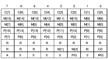
The format of an extended ECId is as follows:
| Bit(s) | Value | Meaning |
|---|---|---|
| C[7:0] | Country (see below) | |
| M[15:0] | Manufacturer (see below) | |
| P[15:0] | Product Type (see below) | |
| R | 0 | mandatory at present |
| 1 | reserved for future use | |
| W[1:0] | 0 | 8-bit code follows after byte 15 of Id space |
| 1 | 16-bit code follows after byte 15 of Id space | |
| 2 | 32-bit code follows after byte 15 of Id space | |
| 3 | reserved | |
| IS | 0 | no Interrupt Status Pointers follow ECId |
| 1 | Interrupt Status Pointers follow ECId | |
| CD | 0 | no Chunk Directory follows |
| 1 | Chunk Directory follows Interrupt Status pointers | |
| A | 0 | Acorn conformant expansion card |
| 1 | non-conformant expansion card | |
| FIQ | 0 | not requesting FIQ (or FIQ relocated) |
| 1 | requesting FIQ | |
| IRQ | 0 | not requesting IRQ (or IRQ relocated) |
| 1 | requesting IRQ |
Every expansion card should have a code for the country of origin. These match those used by the International module, save that the UK has a country code of 0 for expansion cards. If you do not already know the correct country code for your country, you should consult Acorn.
Every expansion card should have a code for manufacturer. If you have not already been allocated one, you should consult Acorn.
Every expansion card type must have a unique number allocated to it. Consult Acorn if you need to be allocated a new product type code.
Reserved fields must be set to zero to cater for future expansion.
This field must currently be set to zero (expansion card is 8 bits wide). For more information, see the earlier Expansion card width.
See the sections entitled Generating interrupts from expansion cards, and Interrupt Status Pointers.
See the chapter entitled Chunk directory structure.
This bit must be zero for expansion cards that conform to this Acorn specification.
If you are using an extended ECId, these bits must be zero, as shown above. A non-zero value shows that you are instead using a simple ECId; for more information see ID field (ID [3:0]).
The section entitledinterrupt status bits are discussed below in the Generating interrupts from expansion cards.
This must be zero, as shown above. For more information, see the chapter entitled Expansion card and extension ROM presence.
An extension ROM must include an extended ECId. This starts at the bottom of the ROM image, and consists of eight bytes as defined above.
For an extension ROM, certain fields within the extended ECId must have particular values:
All expansion cards and extension ROMs must have bit 1 low in the low byte of an ECId (whether simple or extended), so that RISC OS can tell if there are any of them present.
Normally bit 1 of the I/O data bus is pulled high by a weak pullup. Therefore:
Expansion cards must provide two status bits to show if the card is requesting IRQ or FIQ.
If an expansion card only has a simple ECId, then the FIQ and IRQ status bits are bits 2 and 0 respectively in the ECId. If the card does not generate one or both of these interrupts then the relevant bit(s) must be driven low.
If an expansion card has an extended ECId, you must set the IS bit of the ECId and provide Interrupt Status Pointers (see below) if either of the following applies:
If neither of the above apply, then you can omit the Interrupt Status Pointers. The interrupt status bits are located in the low byte of the ECId, and are treated in exactly the same way as for a simple ECId (see above).
To find out more about generating interrupts from expansion cards under RISC OS, you can:
An Interrupt Status Pointer has two 4 byte numbers, each consisting of a 3 byte address field and a 1 byte position mask field. These numbers give the locations of the FIQ and IRQ status bits:
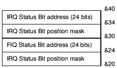
The 24-bit address field must contain a signed 2's-complement number giving the offset from &3240000 (the base of the area of memory into which podules are mapped). Hence the cycle speed to access the status register can be included in the offset (encoded by bits 19 and 20). Bits 14 and 15 (that encode the slot number) should be zero. If the status register is in module space then the offset should be negative: eg &DC0000, which is -&240000.
The 8-bit position mask should only have a single bit set, corresponding to the position of the interrupt status bit at the location given by the address field.
Note that these eight bytes are always assumed to be bytewide. Only the lowest byte in each word should be used.
The addresses may be the same (ie the status bits are in the same byte), so long as the position masks differ. An example of this is if you have had to provide an Interrupt Status Pointer, but do not want to relocate the status bits from the low byte of the ECId; the address fields will both point to the low byte of the ECId, the IRQ mask will be 1, and the FIQ mask will be 4.
If the card does not generate one or both of these interrupts then you must set to zero:
Extension ROMs must have a Chunk Directory, hence they must also provide Interrupt Status Pointers. However, extension ROMs generate neither FIQ nor IRQ; consequently their Interrupt Status Pointers always consist of eight zero bytes.
If the CD bit of an extended ECId is set, then:
The chunks of data and/or code are stored in the expansion card's ROM, or in the extension ROM.
The lengths and types of these Chunks and the manner in which they are loaded is variable, so after the eight bytes of Interrupt Status Pointers there follow a number of entries in the Chunk Directory. The Chunk Directory entries are eight bytes long and all follow the same format. There may be any number of these entries. This list of entries is terminated by a block of four bytes of zeros.
You should note that, from the start of the Chunk Directory onwards, the width of the expansion card space is as set in the ECId width field. From here on the definition is in terms of bytes:
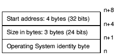
The start address is an offset from the base of the expansion card's address space.
The Operating System Identity Byte forms the first byte of the Chunk Directory entry, and determines the type of data which appears in the Chunk to which the Chunk Directory refers. It is defined as follows:
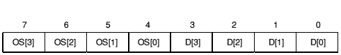
| OS[3] | 0 | reserved | ||
| OS[3] | 1 | mandatory at present | ||
| OS[2:0] | 0 | Acorn Operating System 0: Arthur/RISC OS | ||
| D[3:0] | 0 | Loader | ||
| 1 | Relocatable Module | |||
| 2 | BBC ROM | |||
| 3 | Sprite | |||
| 4-15 | reserved | |||
| 1 | reserved | |||
| D[3:0] | 0-15 | reserved | ||
| 2 | Acorn Operating System 2: UNIX | |||
| D[3:0] | 0 | Loader | ||
| 1-15 | reserved | |||
| 3-5 | reserved | |||
| D[3:0] | 0-15 | reserved | ||
| 6 | manufacturer defined | |||
| D[3:0] | 0-15 | manufacturer specific | ||
| 7 | device data | |||
| D[3:0] | 0 | link | ||
| (for 0, the object pointed to is anotherdirectory) | ||||
| 1 | serial number | |||
| 2 | date of manufacture | |||
| 3 | modification status | |||
| 4 | place of manufacture | |||
| 5 | description | |||
| 6 | part number | |||
| (for 1 - 6, the data in the location pointed to contains the ASCII string of the information.) | ||||
| 7 | Ethernet binary ID (length is always 6 bytes) | |||
| 8 | PCB revision (length is always 4 bytes, treated as a word) | |||
| 9-14 | reserved | |||
| 15 | empty chunk | |||
Those Chunks with OS[2:0] = 7, are operating system independent and are mostly treated as ASCII strings terminated with a zero byte. They are not intended to be read by programs, but rather inspected by users. It is expected that even minimum expansion cards will have an entry for D[3:0] = 5 (description), and it is this string which is printed out by the command *Podules.
For a ROM to be read by the Expansion Card Manager it must conform to the specification, even if only minimally. The simplest way to generate ROM images is to use a BASIC program to combine the various parts together and to compute the header and Chunk Directory structure.
An example program used with an expansion card is shown at the end of this chapter. Its output is a file suitable for programming into a PROM or an EPROM.
The above forms the basis of storing software and data in expansion cards. However, there is an obvious drawback in that the expansion card space is only 4 Kbytes (at word boundaries), and so its usefulness is limited as it stands. To allow expansion cards to accommodate more than this 4 Kbytes an extension of the addressing capability is used. This extension is called the Code Space.
The Code Space is an abstracted address space that is accessed in an expansion card independent way via a software interface. It is a large linear address space that is randomly addressable to a byte boundary. This will typically be used for driver code for the expansion card, and will be downloaded into system memory by the operating system before it is used. The manner in which this memory is accessed is variable and so it is accessed via a Loader.
The purpose of the Loader is to present to the Expansion Card Manager a simple interface that allows the reading (and writing) of the Code Space on a particular expansion card. The usual case is a ROM paged to appear in 2 Kbyte pages at the bottom of the expansion card space, with the page address stored in a latch. This then permits the Expansion Card Manager to load software (Relocatable Modules) or data from an expansion card without having to know how that particular expansion card's hardware is arranged.
The Loader is a simple piece of relocatable code with four entry points and clearly defined entry and exit conditions. The format of the Loader is optimised for ease of implementation and small code size rather than anything else.
The register usage is the same for each of the four entry points.
| Input/Output | Comments | |
|---|---|---|
| R0 | Write/Read data | Treated as a byte |
| R1 | Address | Must be preserved |
| R2-R3 | May be used | |
| R4-R9 | Must be preserved | |
| R10 | May be used | |
| R11 | Hardware | Combined hardware address: must be preserved |
| R12 | Private: must be preserved | |
| R13 | sp | Stack pointer (FD): must be preserved |
| R14 | Return address: use BICS pc, lr, #V_bit | |
| R15 | PC |
The exception to this is the CallLoader entry point where R0 - R2 are the user's entry and exit data.
All code must be relocatable and position independent. It can be assumed that the code will be run in RAM in SVC mode.
| Origin + &00 | Read a byte |
| Origin + &04 | Write a byte |
| Origin + &08 | Reset to initial state |
| Origin + &0C | SWI Podule_CallLoader |
The first call made to the Loader will be to Read address 0, the start of a Chunk directory for the Code Space.
Errors are returned in the usual way; V is set and R0 points at a word-aligned word containing the error number, which is followed by an optional error string, which in turn must be followed by a zero byte. ReadByte and WriteByte may be able to return errors like 'Bad address' if the device is not as big as the address given, or 'Bad write' if using read after write checks on the WriteByte call. If the CallLoader entry is not supported then don't return an error. If Reset fails then return an error.
Since your device drivers may well be short of space, you can return an error with R0=0. The Expansion Card Manager will then supply a default message. Note that this is not encouraged, but is offered as a suggestion of last resort. Errors are returned to the caller by using ORRS pc, lr, #V_bit rather than the usual BICS exit.
Here is an example of a Loader (this example, like all others in this chapter, uses the ARM assembler rather than the assembler included with BBC BASIC V - there are subtle syntax differences):
00                    LEADR  &FFFFFD00       ; Data
00 00003000 PageReg   *      &3000
00 0000000B PageSize  *      11              ; Bits
00 EA00000B Origin    B      ReadByte
04 EA000019           B      WriteByte
08 EA000001           B      Reset
0C E3DEF201           BICS   pc, lr, #V_bit
10 E59FA0E4 Reset     LDR    r10, =2_00000011111111111111000000000000
14 E00BA00A           AND    r10, r11, r10   ; Get hardware address from combined one
18 E28AAA03           ADD    r10, r10, #PageReg
1C E3A02000           MOV    r2, #0
20 E4CA2000           STRB   r2, [ r10 ]
24 E3DEF201           BICS   pc, lr, #V_bit
28 E59F40C4 ReadByte  LDR    r3, =2_00000011111111111111000000000000
2C E00B4004           AND    r3, r11, r3     ; Get hardware address from combined one
30 E284AA03           ADD    r10, r3, #PageReg
34 E3510B3E           CMP    r1, #&F800      ; Last page
38 228F0048           ADRHS  r0, ErrorATB
3C 239EF201           ORRHSS pc, lr, #V_bit
40 E2812B02           ADD    r2, r1, #1 :SHL: PageSize
44 E1A025C2           MOV    r2, r2, ASR #PageSize
48 E4CA2000           STRB   r2, [ r10 ]
4C E3C12BFE           BIC    r2, r1, #&7F :SHL: PageSize
50 E7D40102           LDRB   r0, [ r3, r2, ASL #2 ] ; Word addressing
54 E3DEF201           BICS   pc, lr, #V_bit
58 E28F0000 WriteByte ADR    r0, ErrorNW
5C E39EF201           ORRS   pc, lr, #V_bit
60 00000580 ErrorNW   DCD    ErrorNumber_NotWriteable
64                    DCB    ErrorString_NotWriteable,0
92 00 00              ALIGN
94 00000584 ErrorATB  DCD    ErrorNumber_AddressTooBig
98                    DCB    ErrorString_AddressTooBig,0
AC                    END
The bit masks are used to separate the fields of a combined hardware address - see the description of Podule_HardwareAddress for details of these.
If the Expansion Card Manager is ever asked to 'EnumerateChunk' a Chunk containing a Loader, it will automatically load the Loader. Since RISC OS enumerates all Chunks from all expansion cards at a hard reset this is achieved by default.
If no Loader is loaded then Podule_EnumerateChunks will terminate on the zero at the end of the Chunk Directory in the expansion card space. If, however, when the end of the expansion card space Chunk Directory is reached a Loader has been loaded, then a second Chunk Directory, stored in the Code Space, will appear as a continuation of the original Chunk Directory. This is transparent to the user.
This second Chunk Directory is in exactly the same format as the original Chunk Directory. Addresses in the Code Space Chunk Directory refer to addresses in the Code Space. The Chunk Directory starts at address 0 of the Code Space (rather than address 16 as the one in expansion card Space does).
Each of the four possible internal expansion card slots has four bytes of CMOS RAM reserved for it. These bytes can be used to store status information, configuration, and so on.
You can find the base address of these four bytes by calling Podule_HardwareAddress or Podule_HardwareAddresses.
Most of the SWIs provided by the Expansion Card Manager take a ROM section as a parameter. This identifies the expansion card or extension ROM upon which the command acts. ROM sections used by RISC OS are:
| ROM section | Meaning |
|---|---|
| -1 | System ROM |
| 0 | Expansion card 0 |
| 1 | Expansion card 1 |
| 2 | Expansion card 2 |
| 3 | Expansion card 3 |
| -2 | Extension ROM 1 (not in RISC OS 2) |
| -3 | Extension ROM 2 (not in RISC OS 2) |
| -4 | Extension ROM 3 (etc) (not in RISC OS 2) |
None of the SWIs described in this chapter will act upon the system ROM.
R1 = &45 (reason code)
R1 preserved to pass on (do not claim)
This call is made just before a software generated reset takes place, when the user releases Break. This gives a chance for expansion card software to reset its devices, as this type of reset does not actually cause a hardware reset signal to appear on the expansion card bus. This call must not be claimed.
R1 = &10800 (reason code)
R2 = address of current ST506 hard disc controller
R3 = address of IRQ status register for current hard disc controller
R4 = mask which, when ANDed with IRQ status register, gives non-zero value if IRQs are enabled
R5 = address of IRQ mask register for current hard disc controller
R6 = mask which, when ORd with IRQ mask register, enables IRQ
All registers preserved to pass on, else:
R1 = 0 to claim
R2 = address of new ST506 hard disc controller
R3 = address of IRQ status register for new hard disc controller
R4 = mask which, when ANDed with IRQ status register, gives non-zero value if IRQs are enabled
R5 = address of IRQ mask register for new hard disc controller
R6 = mask which, when ORd with IRQ mask register, enables IRQ
This call is issued by ADFS to enable ST506 hard disc expansion cards to intercept ADFS and use their own hardware rather than the hardware built into the machine. The expansion card should claim the service call, updating the passed registers to the values for its own hardware.
R1 = &10801 (reason code)
R2 = address of current IDE hard disc controller
R3 = address of IRQ status register for current hard disc controller
R4 = mask which, when ANDed with IRQ status register, gives non-zero value if IRQs are enabled
R5 = address of IRQ mask register for current hard disc controller
R6 = mask which, when ORd with IRQ mask register, enables IRQ
R7= address of data read routine for current hard disc controller (0 for default)
R8 = address of data write routine for current hard disc controller (0 for default)
All registers preserved to pass on, else:
R1 = 0 to claim
R2 = address of new IDE hard disc controller
R3 = address of IRQ status register for new hard disc controller
R4 = mask which, when ANDed with IRQ status register, gives non-zero value if IRQs are enabled
R5 = address of IRQ mask register for new hard disc controller
R6 = mask which, when ORd with IRQ mask register, enables IRQ
R7= address of data read routine for new hard disc controller (0 for default)
R8 = address of data write routine for new hard disc controller (0 for default)
This call is issued by ADFS to enable IDE hard disc expansion cards to intercept ADFS and use their own hardware rather than the hardware built into the machine. The expansion card should claim the service call, updating the passed registers to the values for its own hardware.
R1 = &10802 (reason code)
All registers preserved
This call is issued by an IDE expansion card module to warn ADFS of its imminent demise.
R3 = ROM section (see ROM sections)
R0 = expansion card identity byte (ECId)
Interrupt status is unaltered
Fast interrupts are enabled
Processor is in SVC mode
SWI is re-entrant
This call reads into R0 a simple Expansion Card Identity, or the low byte of an extended Expansion Card Identity. It also resets the Loader - if one is present, and has been loaded.
None
R2 = pointer to buffer of 8 or 16 bytes
R3 = ROM section (see ROM sections)
--
Interrupt status is unaltered
Fast interrupts are enabled
Processor is in SVC mode
SWI is re-entrant
This call reads an extended Expansion Card Identity into the buffer pointed to by R2. If the IS bit is set (bit 1 of byte 1) then the expansion card also has Interrupt Status Pointers, and these are also read into the buffer. This call also resets the Loader - if one is present, and has been loaded.
If you do not know whether the card has Interrupt Status Pointers, you should use a 16 byte buffer. Extension ROMs always have Interrupt Status Pointers (although they're always zero), so you should always use a 16 byte buffer for them.
R0 = chunk number (zero to start)
R3 = ROM section (see ROM sections)
R0 = next chunk number (zero if final chunk enumerated)
R1 = size (in bytes) if R0 ![[NOT EQUAL]](../symbols/entities/8800.png) 0 on exit
0 on exit
R2 = operating system identity byte if R0 0 on exit
R4 = pointer to a copy of the module's name if the chunk is a relocatable module (ie if R2 = &81), else preserved
Interrupt status is unaltered by the SWI, but may be altered by the Loader
Fast interrupts are enabled
Processor is in SVC mode
SWI is not re-entrant
This call reads information about a chunk from the Chunk Directory. It returns its size and operating system identity byte. If the chunk is a module it also returns a pointer to a copy of its name; this is held in the Expansion Card Manager's private workspace and will not be valid after you have called the Manager again.
If the chunk is a Loader, then RISC OS also loads it.
To read information on all chunks you should set R0 to 0 and R3 to the correct ROM section. You should then repeatedly call this SWI until R0 is set to 0 on exit.
RISC OS 2 automatically does this on a reset for all expansion cards; if there is a Loader it will be transparently loaded, and any chunks in the code space will also be enumerated. Later versions of RISC OS use Podule_EnumerateChunksWithInfo.
R0 = chunk number
R2 = pointer to buffer (assumed large enough)
R3 = ROM section (see ROM sections)
--
Interrupt status is unaltered by the SWI, but may be altered by the Loader
Fast interrupts are enabled
Processor is in SVC mode
SWI is not re-entrant
This call reads the specified chunk from an expansion card. The buffer must be large enough to contain the chunk; you can use Podule_EnumerateChunks (see Podule_EnumerateChunks) to find the size of the chunk.
None
R0 = offset from start of code space
R1 = number of bytes to read
R2 = pointer to buffer
R3 = expansion card slot number
--
Interrupt status is unaltered by the SWI, but may be altered by the Loader
Fast interrupts are enabled
Processor is in SVC mode
SWI is not re-entrant
This call reads bytes from within an expansion card's code space. It does so using repeated calls to offset 0 (read a byte) of its Loader. RISC OS must already have loaded the Loader; note that the kernel does this automatically on a reset when it enumerates all expansion cards' chunks.
This command returns an error for extension ROMs, because they have neither code space nor a Loader.
None
R0 = offset from start of code space
R1 = number of bytes to write
R2 = pointer to buffer
R3 = expansion card slot number
--
Interrupt status is unaltered by the SWI, but may be altered by the Loader
Fast interrupts are enabled
Processor is in SVC mode
SWI is not re-entrant
This call writes bytes to within an expansion card's code space. It does so using repeated calls to offset 4 (write a byte) of its Loader. RISC OS must already have loaded the Loader; note that the kernel does this automatically on a reset when it enumerates all expansion cards' chunks.
This command returns an error for extension ROMs, because they have neither code space nor a Loader.
None
R0 - R2 = user data
R3 = expansion card slot number
R0 - R2 = user data
Interrupt status is unaltered by the SWI, but may be altered by the Loader
Fast interrupts are enabled
Processor is in SVC mode
Depends on Loader
This call enters an expansion card's Loader at offset 12. Registers R0 - R2 can be used to pass data.
The action the Loader takes will vary from card to card, and you should consult your card's documentation for further details.
If you are developing your own card, you can use this SWI as an entry point to add extra features to your Loader. You may use R0 - R2 to pass any data you like. For example, R0 could be used as a reason code, and R1 and R2 to pass data.
In some hardware designs it may be important to share hardware between the Loader and the driver. You can do so by using this call to call the Loader, which can do hardware accesses for the driver and maintain its own state. For example, if your hardware has a 7 bit page register and a 1 bit output port shared within a single 8 bit latch, the Loader could maintain a flag for the state of the port, and write that bit correctly whenever it writes to the page register.
This command returns an error for extension ROMs, because they have neither code space nor a Loader.
None
Reads bytes directly within an expansion card or extension ROM's address space
R0 = offset from base of a podule's address space (0...&FFF)
R1 = number of bytes to read
R2 = pointer to buffer
R3 = ROM section (see ROM sections)
--
Interrupt status is unaltered
Fast interrupts are enabled
Processor is in SVC mode
SWI is re-entrant
This call reads bytes directly within an expansion card or extension ROM's address space. It is typically used to read from the registers of hardware devices on an expansion card, or to read successive bytes from an extension ROM.
You should use Podule_ReadBytes to read from within an expansion card's code space.
None
Writes bytes directly within an expansion card's address space
R0 = offset from base of a podule's address space (0...&FFF)
R1 = number of bytes to write
R2 = pointer to buffer
R3 = expansion card slot number
--
Interrupt status is unaltered
Fast interrupts are enabled
Processor is in SVC mode
SWI is re-entrant
This call writes bytes directly within an expansion card's address space. It is typically used to write to the registers of hardware devices on an expansion card.
You should use Podule_WriteBytes (see Podule_WriteBytes) to write within an expansion card's code space.
Obviously you cannot write to an extension ROM. You must not use this call to try to write to the ROM area; if you do so, you risk reprogramming the memory and video controllers.
Returns an expansion card or extension ROM's base address, and the address of an expansion card's CMOS RAM
R3 = ROM section (see ROM sections), or base address of expansion card/extension ROM
R3 = combined hardware address
Interrupt status is unaltered
Fast interrupts are enabled
Processor is in SVC mode
SWI is re-entrant
This call returns an expansion card or extension ROM's combined hardware address:
| Bits | Meaning |
|---|---|
| 0 - 11 | base address of CMOS RAM - expansion cards only (4 bytes) |
| 12 - 25 | bits 12 - 25 of base address of expansion card/extension ROM |
| 26 - 31 | reserved |
You can use a mask to extract the relevant parts of the returned value. The CMOS address in the low 12 bits is suitable for passing directly to OS_Byte 161 and 162.
In practice there is little point in finding the combined hardware address of an extension ROM. The base address of the extension ROM is of little use, as the width of the ROM can vary; and extension ROMs do not have CMOS RAM reserved for them.
R0 = chunk number (zero to start)
R3 = ROM section (see ROM sections)
R0 = next chunk number (zero if final chunk enumerated)
R1 = size (in bytes) if R0 0 on exit
R2 = operating system identity byte if R0 0 on exit
R4 = pointer to a copy of the module's name if the chunk is a relocatable module, else preserved
R5 = pointer to a copy of the module's help string if the chunk is a relocatable module, else preserved
R6 = address of module if the chunk is a directly executable relocatable module, or 0 if the chunk is a non-directly-executable relocatable module, else preserved
Interrupt status is unaltered by the SWI, but may be altered by the Loader
Fast interrupts are enabled
Processor is in SVC mode
SWI is not re-entrant
This call reads information about a chunk from the Chunk Directory. It returns its size and operating system identity byte. If the chunk is a module it also returns pointers to copies of its name and its help string, and its address if it is executable. These are held in the Expansion Card Manager's private workspace and will not be valid after you have called the Manager again.
If the chunk is a Loader, then RISC OS also loads it.
To read information on all chunks you should set R0 to 0 and R3 to the correct ROM section. You should then repeatedly call this SWI until R0 is set to 0 on exit.
RISC OS automatically does this on a reset for all expansion cards; if there is a Loader it will be transparently loaded, and any chunks in the code space will also be enumerated.
This call is not available in RISC OS 2, which uses Podule_EnumerateChunks instead.
Returns an expansion card or extension ROM's base address, and the address of an expansion card's CMOS RAM
R3 = ROM section (see ROM sections)
R0 = base address of expansion card/extension ROM
R1 = combined hardware address
Interrupt status is unaltered
Fast interrupts are enabled
Processor is in SVC mode
SWI is re-entrant
This call returns an expansion card or extension ROM's base address, and its combined hardware address:
| Bits | Meaning |
|---|---|
| 0 - 11 | base address of CMOS RAM - expansion cards only (4 bytes) |
| 12 - 25 | bits 12 - 25 of base address of expansion card/extension ROM |
| 26 - 31 | reserved |
You can use a mask to extract the relevant parts of the returned value. The CMOS address in the low 12 bits is suitable for passing directly to OS_Byte 161 and 162.
In practice there is little point in finding the combined hardware address of an extension ROM. The base address of the extension ROM is of little use, as the width of the ROM can vary; and extension ROMs do not have CMOS RAM reserved for them.
This call is not available in RISC OS 2.
--
R0 = number of expansion cards
R1 = number of extension ROMs
Interrupt status is unaltered
Fast interrupts are enabled
Processor is in SVC mode
SWI is re-entrant
This call returns the number of expansion cards and extension ROMs. The number of expansion cards returned is currently always 4, but you must be prepared to handle any other value, including 0.
This call is used by the *Podules command.
This call is not available in RISC OS 2.
None
None
*PoduleLoad expansion_card_number filename [offset]
filename - a valid pathname, specifying a file
offset - offset (in hexadecimal by default) into the Code Space
*PoduleLoad copies the contents of a file into an installed expansion card's RAM, starting at the specified offset. If no offset is given, then a default value of 0 is used.
*PoduleLoad 1 $.Midi.Data 100
*Podules, *PoduleSave
None
Displays a list of the installed expansion cards and extension ROMs
*Podules
None
*Podules displays a list of the installed expansion cards and extension ROMs, using the description that each one holds internally. Some expansion cards and/or extension ROMs - such as one that is still being designed - will not have a description; in this case, an identification number is displayed.
This command still refers to expansion cards as podules, to maintain compatibility with earlier operating systems. This command does not show extension ROMs under RISC OS 2.
*Podules
Podule 0: Midi and BBC I/O podule
Podule 1: Simple podule &8
Podule 2: No installed podule
Podule 3: No installed podule
None
None
*PoduleSave expansion_card_number filename size [offset]
filename - a valid pathname, specifying a file
size - in bytes
offset - offset (in hexadecimal by default) into the Code Space
*PoduleSave copies the given number of bytes of an installed expansion card's ROM into a file. If no offset is given, then a default value of 0 is used.
*PoduleSave 1 $.Midi.Data 200 100
*Podules, *PoduleLoad
None
This program is an example of how to combine the various parts of an expansion card ROM. It also computes the header and Chunk Directory structure. The file it outputs is suitable for programming into a PROM or EPROM:
  10 REM > &.arm.MidiAndI/O.MidiJoiner
  20 REM Author    : RISC OS
  30 REM Last edit : 06-Jan-87
  40 PRINT"Joiner for expansion card ROMs"'"Version 1.05."
  50 PRINT"For Midi board.": DIM Buffer% 300, Block% 20
  70 INPUT'"Enter name of output file : "OutName$
  75 H%=OPENOUT(OutName$)
  80 IF H%=0 THEN PRINT"Could not create '";OutName$;"'.":END
  90 ONERRORONERROROFF:CLOSE#H%:REPORT:PRINT" at line ";ERL:END
 100 Device%=0:L%=TRUE:REPEAT
 120 Max%=&800:REM Max% is the size of the normal area
 130 Low%=&100:REM Low% is the size of the pseudo directory
 140 Base%=0:REM The offset for file address calculations
 150 Rom%=&4000:REM Rom% is the size of BBC ROMs
 170 PROCByte(0):PROCHalf(3):PROCHalf(19):PROCHalf(0):PROCByte(0)
 180 PROCByte(0):PROC3Byte(0):PROCByte(0):PROC3Byte(0)
 190 IF PTR#H% <> 16 STOP
 200 Bot%=PTR#H%:REM Bot% is where the directory grows from
 210 Top%=Max%:REM Top% is where normal files decend from
 230 INPUT"Enter filename of loader : "Loader$
 240 IF Loader$ <> "" THEN K%=FNAddFile( &80, Loader$ )
 250 IF K% ELSE PRINT"No room for loader.":
     PTR#H%=Bot%:PROCByte(0):CLOSE#H%:END
 270 INPUTLINE'"Enter product description : "Dat$
 280 IF Dat$ <> "" THEN PROCAddString( &F5, Dat$ )
 300 PRINT:REPEAT
 310 INPUT"Enter name of file to add : "File$
 320 IF File$ <> "" THEN T%=FNType( File$ ) ELSE T%=0
 330 IF T%=0 ELSE K%=FNAddFile( T%, File$ )
 340 IF K% ELSE PRINT"No more room."
 350 UNTIL (File$ = "") OR (K%=FALSE)
 360 IF K% ELSE PTR#H%=Bot%:PROCByte(0):CLOSE#H%:END
 370 IF L% PROCChange
 390 INPUTLINE"Enter serial number : "Dat$
 400 IF Dat$ <> "" THEN PROCAddString( &F1, Dat$ )
 410 INPUTLINE"Enter modification status : "Dat$
 420 IF Dat$ <> "" THEN PROCAddString( &F3, Dat$ )
 430 INPUTLINE"Enter place of manufacture : "Dat$
 440 IF Dat$ <> "" THEN PROCAddString( &F4, Dat$ )
 450 INPUTLINE"Enter part number : "Dat$
 460 IF Dat$ <> "" THEN PROCAddString( &F6, Dat$ )
 480 Date$=TIME$
 490 Date$=MID$(Date$,5,2)+"-"+MID$(Date$,8,3)+"-"+MID$(Date$,14,2)
 500 PROCAddString( &F2, Date$ )
 530 REM PROCHeader( &F0, Z%+W%*Rom%-Base%, 0 ):REM Link
 550 PTR#H%=Bot%:PROCByte(0)
 570 CLOSE#H%: END
 590 DEF PROCByte(D%):BPUT#H%,D%:ENDPROC
 610 DEF PROCHalf(D%):BPUT#H%,D%:BPUT#H%,D%DIV256:ENDPROC
 630 DEF PROC3Byte(D%)
 640 BPUT#H%,D%:BPUT#H%,D%DIV256:BPUT#H%,D%DIV65535:ENDPROC
 660 DEF PROCWord(D%)
 670 BPUT#H%,D%:BPUT#H%,D%DIV256:BPUT#H%,D%DIV65535
 680 BPUT#H%,D%DIV16777216:ENDPROC
 700 DEF PROCAddString( T%, S$ )
 710 S$=S$+CHR$0
 720 IF L% THEN PROCAddNormalString ELSE PROCAddPsuedoString
 730 ENDPROC
 750 DEF PROCAddNormalString
 760 IF Top%-Bot% < 10+LEN(S$) THEN STOP
 770 PROCHeader( T%, Top%-LEN(S$)-Base%, LEN(S$) )
 780 Top%=Top%-LEN(S$):PTR#H%=Top%:FOR I%=1 TO LEN(S$)
 790 BPUT#H%,ASC(MID$(S$,I%,1)):NEXTI%:ENDPROC
 810 DEF PROCAddPsuedoString
 820 IF Max%+Low%-Bot% < 9 THEN STOP
 830 PROCHeader( T%, Top%-Base%, LEN(S$) )
 840 PTR#H%=Top%:FOR I%=1 TO LEN(S$)
 850 BPUT#H%,ASC(MID$(S$,I%,1)):NEXTI%
 860 Top%=Top%+LEN(S$):ENDPROC
 880 DEF PROCHeader( Type%, Address%, Size% )
 890 PTR#H%=Bot%
 900 PROCByte( Type% )
 910 PROC3Byte( Size% )
 920 PROCWord( Address% )
 930 Bot%=Bot%+8:ENDPROC
 950 DEF FNAddFile( T%, N$ )
 960 F%=OPENIN( N$ )
 970 IF F%=0 THEN PRINT"File '";N$;"' not found.":=FALSE
 980 S%=EXT#F%
 990 IF L% THEN =FNAddNormalFile ELSE =FNAddPsuedoFile
1010 DEF FNAddNormalFile
1020 E%=S%+9-(Top%-Bot%)
1030 IF E%>0 THEN PRINT"Oversize by ";E%;" bytes."':
     PROCChange:=FNAddPsuedoFile
1040 PROCHeader( T%, Top%-S%-Base%, S% )
1050 Top%=Top%-S%:PTR#H%=Top%:FOR I%=1 TO S%
1060 BPUT#H%,BGET#F%:NEXTI%:CLOSE#F%:=TRUE
1080 DEF FNAddPsuedoFile
1090 IF Max%+Low%-Bot% < 9 THEN =FALSE
1100 PROCHeader( T%, Top%-Base%, S% )
1110 PTR#H%=Top%
1120 FOR I%=1 TO S%:BPUT#H%,BGET#F%:NEXTI%
1130 Top%=Top%+S%:CLOSE#F%:=TRUE
1150 DEF PROCChange
1160 PRINT"Changing up.  Wasting ";Top%-Bot%;" bytes."
1170 PTR#H%=Bot%:PROCByte(0):REM Terminate bottom directory
1180 Bot%=Max%:Top%=Max%+Low%:Base%=Max%:L%=FALSE
1190 REM In the pseudo area files grow upward from Top%
1200 ENDPROC
1220 DEF FNType( N$ )
1230 $Buffer%=N$:X%=Block%:Y%=X%/256:A%=5:X%!0=Buffer%
1240 B%=USR&FFDD:IF (B%AND255) <> 1 THEN PRINT"Not a file":=0
1250 V%=(Block%!3)AND&FFFFFF
1260 IFV%=&FFFFFA THEN =&81
1270 IF((Block%!2AND&FFFF)=&8000)AND((Block%!6AND&FFFF)=&8000)THEN=&82
1280 IFV%=&FFFFF9 THEN =&83
1290 =0