
|
www.riscos.com Technical Support: |
Click Select on the application icon. This displays the SetUp dialogue box:
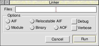
This allows you to set the following options:
The Files writable icon allows you to enter the list of object and library files to be linked. You can do this in two ways:
Note: When linking libraries, you must take care to link them in the correct order. See the chapter entitled Libraries.
AIF generates ARM Image Format (AIF) output. This is the default image used for building an application. You should only choose other image types if AIF is not suitable for some reason. The format of AIF files is described in Appendix E.
Module generates Relocatable Module Format (RMF) output. Refer to Relocatable modules in the Acorn C/C++ manual for more details on relocatable modules.
Relocatable AIF links an image so that it can be run at any address, usually specified in conjunction with the Workspace option on the SetUp menu. See the chapter entitled Relocatable AIF images for more details.
Binary generates a plain binary image (without an image header or any specific image format). The default load address for a binary image is 0. Any other address can be specified using the Base option from Link's SetUp menu. If AIF is also enabled in Link's SetUp dialogue box, then a plain binary image is generated, preceded by an AIF header which describes it.
AOF generates partially linked output in ARM Object Format, suitable for inclusion in a subsequent link step.
Debug allows you to debug a program with the desktop debugger DDT. See the chapter entitled Desktop debugging tool for more details on preparing a program for use with the debugger. This option is not suitable for use with the module option. This option is switched off by default.
Verbose gives progress reports in the Output window while linking. See the chapter entitled Output for an example of this output. This option is switched off by default.
Clicking Menu on the SetUp dialogue box displays the menu shown on the left.
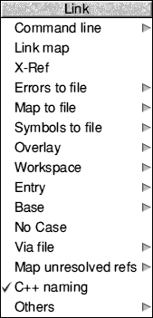
Command line allows you to specify the command line to be presented to the underlying Link command line tool. Refer to the Command line interface for more details.
Link map displays the base address and size of every code, data and debugging information area, and displays total sizes for the code, data and debugging information in the output window. See the chapter entitled Link map option for more information. For details on linker areas, see the chapter entitled AOF.
X-Ref displays a list of inter-area references. This option is most useful when trying to reduce dependencies between library elements, so that you only need include the minimum set of library elements. It is also useful when using overlays. See the chapter entitled X-Ref option for more details.
Errors to file allows you to specify the name of a file to which all errors should be written.
Map to file will write a link map to the given filename (if the Link map option is enabled).
Symbols to file will write all symbols found to a file with the given name.
Overlay generates an overlaid image using the specified overlay description file. For details of overlay description files, see the chapter entitled Overlay description files. This option is not suitable for use when generating Module or Binary output.
Workspace, when used in conjunction with the Relocatable AIF option, generates an auto-relocatable image which will relocate itself to the top of its application space. This leaves the specified amount of workspace above the image free for the use of the program being linked. The effect of this option is not currently defined when generating image types other than relocatable AIF.
Entry specifies the entry point of an image if none of the object files themselves specify an entry point. Generally, you should only use it when writing completely in assembler without using the assembler's ENTRY directive.
Base specifies the base address at which the image should be linked. By default this is &8000 for AIF images and 0 for binary images. You should always load non-relocatable AIF images at their base address.
No case causes a case insensitive comparison to be used when comparing symbols. You will not generally want to use this option with C (which is case sensitive). However, you may need to use it with other language systems (such as Pascal and Fortran) which are case insensitive, especially if you are trying to interwork with C and one of these languages.
Via file allows you to set up a list of object files to be linked in one file called a Via file. Instead of having to drag all the files to the Files list on the SetUp dialogue box, just enter the name of the Via file in the submenu.
Map unresolved refs causes all unresolved references to be resolved to a given symbol.
C++ naming will report C++ symbol names using C++ notation.
Note that you must enable this option when linking C++ compiled code.
Others allows you to specify other options allowed by the underlying command line link tool.
Note: The Base, Workspace and Entry options require a numeric argument to be entered in the associated submenu. You can prefix this argument by & or 0X to specify a hexadecimal value. You can postfix it by k for 210 and m for 220.
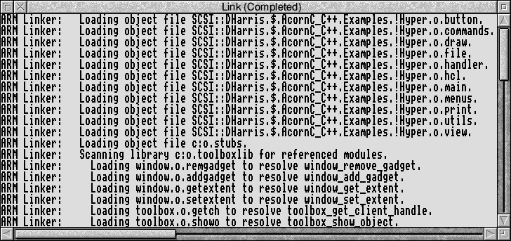
The Output window displays information printed when you have selected the Verbose, Link map or X-Ref options. It also displays any error messages generated while linking.
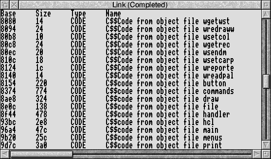
The following windows show examples of the Verbose and Link map output. You will find an example of the X-Ref output in the X-Ref option.
Two common errors which can occur during a link stage are caused by unresolved and multiple references.
In the case of unresolved references, a symbol has been referenced from an object file, but there is no corresponding definition for the symbol. Link will generate an error message giving the name of the undefined symbol. This is usually caused by the omission of a required object or library file from the file list, or the misspelling of an external identifier in the original source program.
Multiple references are caused by a clash of names. For example, a procedure might have been defined with the same name as a library procedure, or as a procedure in another object file.
Libraries differ from object files in the way Link uses them. First, all the object files are linked together. Then, for each library in turn, Link searches for symbol definitions which match unsatisfied symbol references. When such a symbol definition is found, the module defining that symbol is loaded.
When a library module is loaded, new unsatisfied symbol references may be created, so the library is re-searched until no more members are loaded from it. Note that each library is processed in turn, so references between libraries must be ordered.
A reference from a member of a library later in the file list to a member earlier in the file list will not be resolved. Therefore you must drag libraries to the file list in the correct order.
Usually, at least one library file will be specified in the list of files to be linked. This will typically be the run-time library for the language you are using. When writing in C, you can use either the shared library (in which case you will need to link with the shared library stubs, C:o.stubs) or the unshared library, C:o.ansilib. Use the unshared library when linking a program for use with the desktop debugger, or when linking a program which you intend to distribute to people who may not have the shared C library.
You can call the procedures in the library for one language from programs written in another, provided:
Refer to the chapter The Shared C library in Volume 4 of the RISC OS 3 Programmer's Reference Manual for details on how to initialise the common run-time kernel distributed with the C library.
An introduction to overlays is given in the Acorn C/C++ manual. If you are not familiar with the concept of overlays, you should read the chapter on overlays in that manual first. This section only describes how to use Link to create an overlaid application.
A simple, 2-dimensional, static overlay scheme is supported. There is one root segment, and as many memory partitions as you specify (called 1_N, 2_N, etc). Within each partition, some number of overlay segments (called 1_1, 1_2, etc) share the same area of memory. You specify the contents of each overlay segment and Link calculates the size of each partition, allowing sufficient space for the largest segment in it. All addresses are calculated at link time: overlaid programs are not relocatable.
A hypothetical example of the memory map for an overlaid program might be:
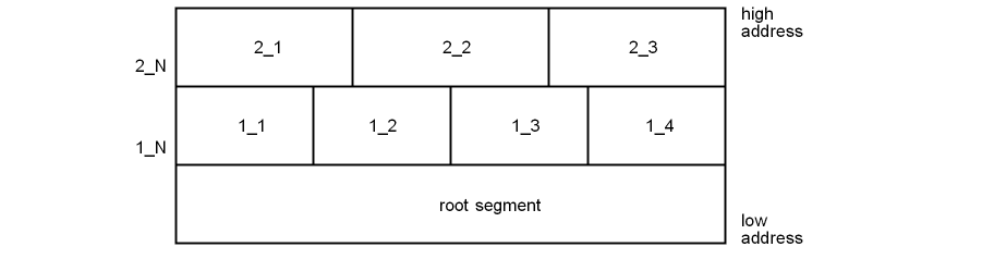
Segments 1_1, 1_2, 1_3 and 1_4 share the same area of application workspace. Only one of these segments can be in memory at any given instant; the remainder must be on disc.
Similarly segments 2_1, 2_2 and 2_3 share the 2_N area of memory, which is entirely separate from the 1_N partition.
Link assigns AOF AREAs to overlay segments under user control. Usually, a compiler produces one code AREA and one data AREA for each source file (called C$$code and C$$data when generated by the C compiler). The C compiler option -zo (described in the Acorn C/C++ manual) allows each separate function to be compiled into a separate code AREA. This gives finer control of the assignment of functions to overlay segments (but at the cost of slightly enlarged code and enlarged object files). You control the overlay structure by describing the assignment of certain AREAs to overlay segments.
For all remaining code AREAs, Link will act as follows:
If all references to the AREA are from the same overlay segment, the AREA is included in that segment; otherwise, the AREA is included in the root segment.
This strategy can never make an overlaid program use more memory than if Link put all remaining AREAs in the root segment, but it can sometimes reduce it.
By default, only code AREAs are included in overlay segments. Data AREAs can be forcibly included, but it is the user's responsibility to ensure that doing so is meaningful and safe.
On disc, an overlaid program is organised as a RISC OS application. The components of the application (the !RunImage and the various overlay segments) must reside in the application directory. Link creates the following components in the application directory:
| !RunImage | The root segment, an AIF image (which may be squeezed). |
| 1_1 ... 2_1 ... | Overlay segments, which are plain binary images, linked at absolute 1_2 addresses. Overlay segments may not be squeezed. |
The overlay description file, specified in the overlay submenu, describes the required overlay structure. It is a sequence of logical lines:
Each logical line has the following structure:
segment_name module_name [(list_of_AREA_names)] module_name ...
For example:
1_1 edit1 edit2 editdata(C$$code,C$$data) sort
The list_of_AREA_names is a comma-separated list of names as they appear when displayed by the DecAOF tool. If omitted, all code AREAs are included.
A module_name is either the name of an object file (with all leading pathname segments removed) or the name of a library member (again, with all leading pathname segments removed).
To help the user-partition between overlay segments, Link can generate a list of inter-AREA references. To do this, choose the X-Ref option on the SetUp menu. The following window shows an example of the output from X-Ref:
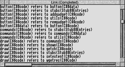
In general, if area A references area B (for example because x in area A calls y in area B) then A and B should not share the same area of memory. Otherwise, every time x calls y or y returns to x, there will be an overlay swap.
The Link map option displays the base address and size of every area in the output program. It is useful for determining how AREAs might be packed most efficiently into overlay segments.
The overlay manager is responsible for loading overlay segments when:
In general, referencing a datum cannot cause an overlay segment to be loaded. One exception to this is an indirect procedure call via a function pointer which will cause an overlay segment to be loaded (Link cannot distinguish this from a normal procedure call, since Link just sees a word relocation to an overlaid procedure). Note that the pointer itself must not be overlaid.
If Link detects a data reference to a non co-resident or potentially non co-resident segment it will issue one of the following messages:
Non co-resident data reference in module_name(area_name)

Possible non co-resident data reference in module_name(area_name)
Certain types of data reference cannot be detected by Link. This happens when read-only data is placed in a code segment. The C compiler places string literals in code areas. This will cause problems if you have external string literals, since Link cannot distinguish between a string literal and a procedure in the code segment. Hence it indirects the string through the Procedure Call Indirection Table (PCIT). So, when your program reads the contents of the string, it will in fact end up reading the contents of the PCIT.
The C compiler option -fw (described in the Acorn C/C++ manual) causes the compiler to place string literals in data areas. You should use this option on modules which may contain external string literals.
The overlay manager must be included in the link stage. You will find the overlay manager in the object file C:o.overmgr. You should drag this object file to the Files icon when linking an overlaid program.
Note: The overlay manager is also contained in the non-shared library ANSILib, so, if you are using ANSILib, you do not need to drag the overlay manager to the Files icon. The shared C library does not contain a copy of the overlay manager.
Usually, when an image file is produced, it will execute correctly only at the specified base address (or the default of &8000 if a base is not specified). This is because the program will contain references to absolute addresses within itself. However if you tell Link to generate a relocatable AIF image, you can load and execute the program at any address. Link also inserts a branch in the image header, so that the relocation code is automatically called when you run the program.
This is achieved by adding the following to the end of the image:
The relocation table is a list of offsets from the start of the program to words which need relocating. These words are adjusted by the difference between the base address of the program and the address where it was loaded. Once the relocation has been performed, the program proper starts executing.
However, although this can be used to make a program statically relocatable, it does not confer true position-independence on the program. That is, the program cannot be moved in memory once it has started, and still be expected to work.
If a Workspace value is specified on the SetUp menu, Link inserts the value in the image header. The relocation code examines this value and, if the value is non-zero, relocates the application to the top of application space, leaving the specified amount of workspace between the end of the application and the top of application space for stack and heap usage.
Utility or transient programs (filetype FFC) can be linked as relocatable AIF images. Use the SetType command to set the filetype correctly after linking:
*SetType image Utility
Notes: The C library cannot be used when linking a utility. Utility programs must not be squeezed. For more details on utilities, refer to the RISC OS 3 Programmer's Reference Manual.
When linking a relocatable module, Link performs a similar task as when linking a relocatable AIF image, adding a relocation table and a relocation routine to the end of the module image.
However, the mechanism by which the relocation routine is called is different in a relocatable module: A module must be multiply relocatable, since it may move about in the Relocatable Module Area (RMA) when, for example, the RMA is tidied with the *RMTidy command. The module must call the relocation routine in its initialisation (or re-initialisation) code.
When using the C Module Header Generator (CMHG) tool you need not worry about this, since CMHG automatically generates a module header which includes a call to the relocation routine in its initialisation code.
If you are constructing the module header in assembler, you must make this call yourself. Use the IMPORT directive to import the external symbol __RelocCode and place a BL to this symbol in your initialisation code.
        IMPORT  |__RelocCode|
init
        ...
        BL     |__RelocCode|
        ...
Note: any code executed before the call to the relocation routine must be position-independent.
When creating a module header in assembler, the AREA containing the header should have the attributes CODE and READONLY. The AREA name should be chosen so that the AREA will be the first AREA in the module. Link sorts AREAs first by attribute, then by AREA name, so you should choose an AREA name which is lexicographically less than all other AREA names in your module. The CMHG tool uses an AREA name of !!!Module$$Header, but this is not obligatory.
All symbols containing the substring $$ are reserved by Acorn for use by Link.
For each AREA in the output file formed by coalescing one or more areas of the same name (e.g. C$$code) Link generates two symbols:
| area_name$$Base | Address of the start of the area. |
| area_name$$Limit | Address of the byte beyond the end of the area. |
| area_name | The name of the area in the output file. You can use these symbols in your programs to refer to the Base and Limit of areas in your programs. |
In addition, Link creates four conceptual areas in the output, and defines Base and Limit symbols for them.
| Image$$RO$$Base | Address of the start of the read-only (code) area. |
| Image$$RO$$Limit | Address of the byte beyond the end of the code area. |
| Image$$RW$$Base | Address of the start of the read/write (data) area. |
| Image$$RW$$Limit | Address of the byte beyond the end of the data area. |
| Image$$ZI$$Base | Address of the start of the zero-initialised (bss) area. |
| Image$$ZI$$Limit | Address of the byte beyond the end of the bss area. |
Although it will often be the case, there is no guarantee that the end of the read-only area corresponds to the start of the read/write area. You should not therefore rely on this being true.
The read/write (data) area may contain code, as programs are sometimes self-modifying. Similarly, the read-only (code) area may contain read-only data (e.g. strings, floating-point constants etc).
The format of the Link command is:
Link options file_list
Abbreviations are shown capitalised.